We make complete product assemblies. Assembling PCBA into plastic enclosures are the most typical process.
Just like the PCB assembly, We produce plastic moulds / injections parts in house. This gives our customer great advantage in terms of quality control, delivery and cost.
Having a deep knowledge in plastic mould/injections differentiate Fumax from other pure PCB assembly factory. Customers are happy to get complete turn key solution for finished products from Fumax. Working with Fumax becomes so much easier from start to finished product.
The most typical Plastic material we work with are ABS, PC, PC/ABS, PP, Nylon, PVDF, PVC, PPS, PS, HDPE, etc…
Following is a case study of a product that consists of PCB boards, plastics, wires, connectors, programming, testing, package…etc all the way to a final product – ready to sell.
General manufacturing flow
| Step number | Manufacturing step | Test/inspection step |
| 1 | Incoming inspection | |
| 2 | AR9331 memory programming | |
| 3 | SMD assembly | SMD assembly inspection |
| 4 | Through hole assembly | AR7420 memory programming |
| PCBA testing | ||
| Visual inspection | ||
| 5 | Mechanical assembly | Visual inspection |
| 6 | Burn-in | |
| 7 | Hipot test | |
| 8 | Performance PLC test | |
| 9 | Labels print | Visual inspection |
| 10 | FAL test bench | |
| 11 | Packaging | Output control |
| 12 | External Inspection |
Product Manufacturing Specification for Smart Master G3
1. FORMALISM
1.1 Abbreviations
| AD | Applicable Document |
| AC | Alternative Current |
| APP | APPlication |
| AOI | Automatic Optical Inspection |
| AQL | Acceptable Quality Limit |
| AUX | AUXiliary |
| BOM | Bill Of Material |
| COTS | Commercial Off The Shelf |
| CT | Current Transformer |
| CPU | Central Processor Unit |
| DC | Direct Current |
| DVT | Design Validation Test |
| ELE | ELEctronic |
| EMS | Electronic Manufacturing Service |
| ENIG | Electroless Nickel Immersion Gold |
| ESD | ElectroStatic Discharge |
| FAL | Final Assembly Line |
| IPC | The Association Connecting Electronics Industries, formerly Institute for Printed Circuits |
| LAN | Local Area Network |
| LED | Light Electroluminescent Diode |
| MEC | MEChAnical |
| MSL | Moisture Sensitive Level |
| NA | None Applicable |
| PCB | Printed Circuit Board |
| PLC | PowerLine Communication |
| PV | PhotoVoltaic |
| QAL | QuALity |
| RDOC | Reference DOCument |
| REQ | REQuirements |
| SMD | Surface Mounted Device |
| SOC | System On Chip |
| SUC | SUpply Chain |
| WAN | Wide Area Network |
1.2 Codifications
→ Documents Listed as RDOC-XXX-NN
Where “XXXX” can be: SUC, QAL, PCB, ELE, MEC or TST Where “NN” is the number of the document
→ Requirements
Listed as REQ-XXX-NNNN
Where “XXXX” can be: SUC, QAL, PCB, ELE, MEC or TST
Where “NNNN” is the number of the requirement
→ Sub-assemblies Listed as MLSH-MG3-NN
Where “NN” is the number of the sub assembly
1.3 Document versioning management
Sub-assemblies and documents have their versions registered in the document: FCM-0001-VVV
Firmwares have their versions registered in the document: FCL-0001-VVV
Where “VVV” is the document version.
2 Context and object
This document gives the Smart Master G3 manufacturing requirements.
A Smart Master G3 hereafter designated as “product”, is the integration of several elements as electronics and mechanicals parts but stays mainly an electronic system. It’s why Mylight Systems (MLS) is looking for an Electronic Manufacturer Service (EMS) in order to manage the whole manufacturing of the product.
This document must allow a subcontractor to give to Mylight Systems a global offer about the manufacturing of the product.
Aims of this document are to:
– Give technical data about the manufacturing of the product,
– Give quality requirements to ensure the conformity of the product,
– Give supply chain requirements to ensure the cost and the cadency of the product.
The EMS subcontractor must answer to 100% of requirements of this document.
No requirements can be changed without MLS agreement.
Some requirements (marking as “EMS design asked”) ask the subcontractor to give an answer to a technical point, like quality controls or packaging. These requirements are left open for the EMS subcontractor to suggest one or several answers. MLS will then validate the answer.
MLS must be in direct relationship with the selected EMS subcontractor, but the EMS subcontractor can select and manage itself others subcontractors with MLS approval.
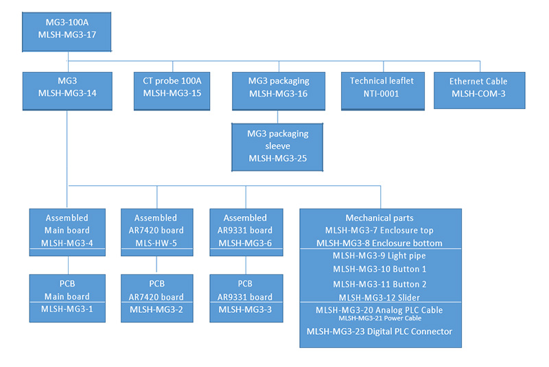
3 .Assembly breakdown structure
3.1 MG3-100A
4.General manufacturing flow
| Step number | Manufacturing step | Test/inspection step |
| 1 | Incoming inspection | |
| 2 | AR9331 memory programming | |
| 3 | SMD assembly | SMD assembly inspection |
| 4 | Throughole assembly | AR7420 memory programming |
| PCBA testing | ||
| Visual inspection | ||
| 5 | Mechanical assembly | Visual inspection |
| 6 | Burn-in | |
| 7 | Hipot test | |
| 8 | Performance PLC test | |
| 9 | Labels print | Visual inspection |
| 10 | FAL test bench | |
| 11 | Packaging | Output control |
| 12 | External Inspection |
5.Supply chain requirements
| Supply chain documents | |
| REFERENCE | DESCRIPTION |
| RDOC-SUC-1. | PLD-0013-CT probe 100A |
| RDOC-SUC-2. | MLSH-MG3-25-MG3 Packaging sleeve |
| RDOC-SUC-3. | NTI-0001-Notice d’installation MG3 |
| RDOC-SUC-4. | GEF-0003-Gerber file of AR9331 board of MG3 |
REQ-SUC-0010: Cadency
The selected subcontractor must be able to make up to 10K products a month.
REQ-SUC-0020: Packaging
(EMS design asked)
The shipment packaging is under the responsibility of the subcontractor.
The shipment packaging must allow the products to be transported by sea, air and roads.
The shipment packaging description must be given to MLS.
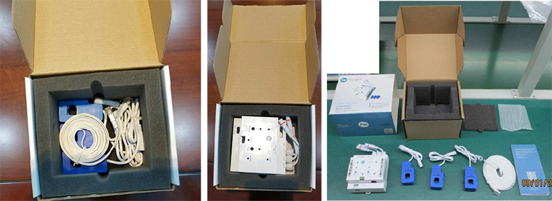
The shipment packaging must include (see Fig 2):
– The product MG3
– 1 standard carton (example: 163x135x105cm)
– Internal carton protections
– 1 charming outer sleeve (4 faces) with Mylight logo and different information. See RDOC-SUC-2.
– 3 CT probes. See RDOC-SUC-1
– 1 Ethernet cable: flat cable, 3m, ROHS, 300V isolation, Cat 5E or 6, CE, 60°c minimum
– 1 Technical leafletRDOC-SUC-3
– 1 external label with identification information (text and bar code) : Reference, Serial number, PLC MAC address
– Plastic bag protection if possible (to discuss)

REQ-SUC-0022: Large packaging type
(EMS design asked)
The subcontractor must give how delivery unit packages inside larger packages.
Maximum number of unit package 2 is 25 inside a large carton.
Identification information of each unit (with a QR code) must be visible with an external label on each large package.
REQ-SUC-0030: PCB supply
The subcontractor must be able to supply or to manufacture the PCB.
REQ-SUC-0040: Mechanical supply
The subcontractor must be able to supply or to manufacture the plastic enclosure and all mechanical parts.
REQ-SUC-0050: Electronic components supply
The subcontractor must be able to supply all electronics components.
REQ-SUC-0060: Passive component selection
In order to optimize costs and logistic method, the subcontractor can suggest the references to be used for all passive components which are specified as “generic” in RDOC-ELEC-3. Passive components must comply with the description column RDOC-ELEC-3.
All selected components must be validated by MLS.
REQ-SUC-0070: Global cost
The objective EXW cost of the product must be given in a dedicated document and can be revised every year.
REQ-SUC-0071: detailed cost
(EMS design asked)
The cost must be detailed with minimum:
– BOM of each electronic assembly, mechanicals parts
– Assemblies
– Tests
– Packaging
– Structural costs
– Margins
– Expedition
– Industrialization costs : benches, tools, process, pre-series…
REQ-SUC-0080: Manufacturing file acceptance
The manufacturing file must be fully completed and accepted by MLS before pre series and mass production.
REQ-SUC-0090: Manufacturing file changes
Any change inside the manufacturing file must be reported and accepted by MLS.
REQ-SUC-0100: Pilot run qualification
A pre series qualification of 200 products is asked before starting mass production.
Defaults and issues found during this pilot run must be reported to MLS.
REQ-SUC-0101: Pre series reliability test
(EMS design asked)
After Pilot run manufacturing, reliability tests, or Design Validation Test (DVT) must be done with minimum:
– Quick temperature cycles -20°C / +60°C
– PLC performance tests
– Internal temperature checks
– Vibration
– Drop test
– Full functionality tests
– Buttons stress tests
– Long time burn in
– Cold/hot start
– Humidity start
– Power cycles
– Custom connectors impedance checking
– …
Detailed test procedure will be given by the subcontractor and must be accepted by MLS.
All failed tests must be reported to MLS.
REQ-SUC-0110: Manufacturing order
All manufacturing order will be done with below information:
– Reference of the asked product
– Quantities of products
– Packaging definition
– Price
– Hardware version file
– Firmware versions file
– Personalization file (with MAC address and serial numbers)
If any of this information is missed or is not clear, the EMS mustn’t start the production.
6 Quality requirements
REQ-QUAL-0010: Storage
PCB, electronic components and electronic assemblies must be stored in humidity and temperature-controlled room:
– Relative humidity below 10%
– Temperature between 20°C and 25°C.
The subcontractor must have a MSL control procedure and give it to MLS.
REQ-QUAL-0020: MSL
PCB and several components identified in the BOM are subject to MSL procedures.
The subcontractor must have a MSL control procedure and give it to MLS.
REQ-QUAL-0030: RoHS/Reach
The product must be RoHS compliance.
The subcontractor must inform MLS of any substance used in the product.
As example, the subcontractor must inform MLS of which glue/solder/cleaner are used.
REQ-QUAL-0050: Subcontractor quality
The subcontractor must be certified ISO9001.
The subcontractor must give its ISO9001 certificate.
REQ-QUAL-0051: Subcontractor quality 2
If the subcontractor works with others subcontractors, they must be also be certified ISO9001.
REQ-QUAL-0060: ESD
All electronic components and electronic boards must be manipulated with ESD protection.
REQ-QUAL-0070: Cleaning
(EMS design asked)
Electronics boards must be cleaned if needed.
Cleaning must not damage sensitive parts like transformers, connectors, markings, buttons, indcutors…
The subcontractor must give to MLS its cleaning procedure.
REQ-QUAL-0080: Incoming inspection
(EMS design asked)
All electronic components and PCB batches must have an incoming inspection with AQL limits.
Mechanical parts must have a dimension incoming inspection with AQL limits if they are outsourced.
The subcontractor must give to MLS its incoming control procedures including AQL limits.
REQ-QUAL-0090: Output control
(EMS design asked)
The product must have an output control with minimum sample inspections and AQL limits.
The subcontractor must give to MLS its input control procedures including AQL limits.
REQ-QAL-0100: Storage of rejected products
Each product that does not pass a test or a control, no matter which test, must be stored by the MLS subcontractor for Quality Investigation.
REQ-QAL-0101: Rejected products information
MLS must be informed of any event which can create rejected products.
MLS must be informed about number of rejected products or any batches.
REQ-QAL-0110: Reporting on Manufacturing Quality
The EMS subcontractor must report to MLS for every production batch the quantity of rejected products per test or control stage.
REQ-QUAL-0120: Traceability
All controls, tests and inspections must be stored and dated.
Batches must be clearly identified and separated.
References used in products must be traceable (exact reference and batch).
Any change to any reference must be notified to MLS before implementation.
REQ-QUAL-0130: Global rejection
MLS can return a complete batch if the rejection due to the subcontractor is above 3% in less of 2 years.
REQ-QUAL-0140: Audit /external inspection
MLS is allowed to visit the subcontractor (including its own subcontractors) to ask quality reports and to do inspections tests, at least 2 times a year or for any batch of production. MLS can be represented by a third-party company.
REQ-QUAL-0150: Visual inspections
(EMS design asked)
The product has some visual inspections mentioned inside the general manufacturing flow.
These inspection means:
– Check of drawings
– Check of correct assemblies
– Check of labels/stickers
– Checks of scratches or any visual defaults
– Soldering reinforcement
– Check of a heatshrinks around fuses
– Check of directions of cables
– Checks of glues
– Check of melting points
The subcontractor must give to MLS its Visual inspections procedures including AQL limits.
REQ-QUAL-0160: General manufacturing flow
Order of each step of the General manufacturing flow must be respected.
If for any reasons, as for example reparability, a step must be done again, all steps after must be done also again in particular Hipot testing and FAL test.
7 PCBs requirements
The product is composed of three different PCB
| PCB documents | |
| REFERENCE | DESCRIPTION |
| RDOC-PCB-1. | IPC-A-600 Acceptability of Printed Boards |
| RDOC-PCB-2. | GEF-0001-Gerber file of main board of MG3 |
| RDOC-PCB-3. | GEF-0002-Gerber file of AR7420 board of MG3 |
| RDOC-PCB-4. | GEF-0003-Gerber file of AR9331 board of MG3 |
| RDOC-PCB-5. | IEC 60695-11-10:2013 : Fire hazard testing – Part 11-10: Test flames – 50 W horizontal and vertical flame test methods |
REQ-PCB-0010: PCB characteristics
(EMS design asked)
Main characteristics below must be respected
| Characteristics | Values |
| Numbers of layers | 4 |
| External copper thickness | 35µm / 1oz min |
| Size of PCBs | 840x840x1.6mm (main board), 348x326x1.2mm (AR7420 board), |
| 780x536x1mm (AR9331 board) | |
| Internal copper thickness | 17µm / 0.5oz min |
| Minimum isolation/route width | 100µm |
| Minimum solder mask | 100µm |
| Minimum via diameter | 250µm (mechanical) |
| PCB material | FR4 |
| Minimum thickness between | 200µm |
| external copper layers | |
| Silkscreen | Yes on top and bottom, white color |
| Soldermask | Yes, green on top and bottom, and above all vias |
| Surface finishing | ENIG |
| PCB on Panel | Yes, can be adjusted on demand |
| Via filling | No |
| Solder mask on via | Yes |
| Materials | ROHS/REACH/ |
REQ-PCB-0020: PCB testing
Nets isolation and conductance must be 100% tested.
REQ-PCB-0030: PCB marking
Marking of PCBs is allowed only on the dedicated area.
PCBs must be marked with the reference of the PCB, its version and the date of manufacturing.
MLS reference must be used.
REQ-PCB-0040: PCB manufacturing files
See RDOC-PCB-2, RDOC-PCB-3, RDOC-PCB-4.
Be careful, characteristics in REQ-PCB-0010 are the main information and must be respected.
REQ-PCB-0050: PCB quality
Following IPC-A-600 class 1. See RDOC-PCB-1.
REQ-PCB-0060: Inflammability
Materials used in PCB must be compliant with CEI 60695-11-10 de V-1. See RDOC-PCB-5.
8 Assembled electronic requirements
3 electronics board must be assembled.
| Electronic documents | |
| REFERENCE | TITLE |
| RDOC-ELEC-1. | IPC-A-610 Acceptability of Electronic Assemblies |
| RDOC-ELEC-2. | GEF-0001-Gerber file of main board of MG3 RDOC |
| ELEC-3. | GEF-0002-Gerber file of AR7420 board of MG3 RDOC |
| ELEC-4. | GEF-0003-Gerber file of AR9331 board of MG3 RDOC |
| ELEC-5. | BOM-0001-BOM of main board of MG3 RDOC-ELEC-6. |
| BOM-0002 | BOM file of AR7420 board of MG3 RDOC-ELEC-7. |
| BOM-0003 | BOM file of AR9331 board of MG3 |
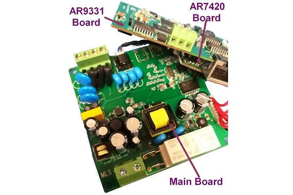
Fig 3. Example of electronic assembled electronic boards
REQ-ELEC-0010: BOM
The BOM RDOC-ELEC-5, RDOC-ELEC-6,and RDOC-ELEC-7 must be respected.
REQ-ELEC-0020: Assembly of SMD components:
SMD components must be assembled with an automatic assembly line.
See RDOC-ELEC-2, RDOC-ELEC-3, RDOC-ELEC-4.
REQ-ELEC-0030: Assembly of through hole components:
Through hole components must be mounted with selective wave or manually.
Residual pins must be cut below 3mm of height.
See RDOC-ELEC-2, RDOC-ELEC-3, RDOC-ELEC-4.
REQ-ELEC-0040: Soldering reinforcement
Soldering reinforcement must be done below the relay.
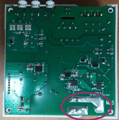
Fig 4. Soldering reinforcement on the main board bottom
REQ-ELEC-0050: Heat Shrink
Fuses (F2, F5, F6 on main board) must have a heat shrink in order to avoid internal parts to be injected inside the enclosure in case of overintensity.
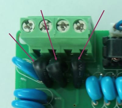
Fig 5. Heat shrinks around fuses
REQ-ELEC-0060: Rubber protection
No rubber protection is needed.
REQ-ELEC-0070: CT probes connectors
Female CT probes connectors must be soldered manually to the main board as in the figure below.
Use the reference MLSH-MG3-21 connector.
Take care of the color and the direction of cable.
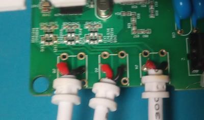
Fig 6. Assembly of CT probes connectors
REQ-ELEC-0071: CT probes connectors glue
Glue need to be added on CT probes connector to protect them against vibration/manufacturing misuse.
See Figure below.
The glue reference is inside RDOC-ELEC-5.
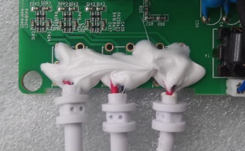
Fig 7. Glue on CT probes connectors
REQ-ELEC-0080: Tropicalization:
No tropicalization is asked.
REQ-ELEC-0090: Assembly AOI inspection:
100% of the board must have AOI inspection (soldering, orientation and marking).
All boards must be inspected.
The detailed AOI program must be given to MLS.
REQ-ELEC-0100: Passive components controls:
All passive components must be checked before reporting on the PCB, at minimum with a human visual inspection.
The detailed passive components control procedure must be given to MLS.
REQ-ELEC-0110: X ray inspection:
No X ray inspection are asked but temperature cycle and functional tests must be done for any change in the SMD assembly process.
Temperature cycle tests must be done for each production tests with AQL limits.
REQ-ELEC-0120: Reworking:
Manual reworking of electronics boards is allowed for all components except for integer circuits: U21/U22 (AR7420 board), U3/U1/U11(AR9331 board).
Automatic reworking is allowed for all components.
If a product is disassembly to do rework because it fails on the final test bench, it must do again the Hipot test and the final test.
REQ-ELEC-0130: 8pins connector between AR9331 board and AR7420 board
J10 connectors are used to connect board AR9331 and board AR7420. This assembly must be done manually.
The reference of the connector to use is MLSH-MG3-23.
The connector has 2mm pitch and its height is 11mm.
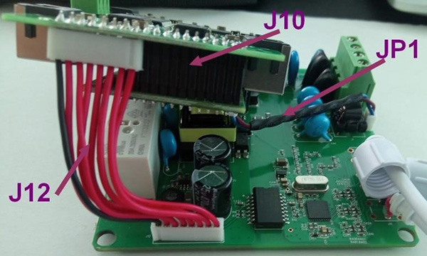
Fig 8. Cables and connectors between electronics boards
REQ-ELEC-0140: 8pins connector between Main board and AR9331 board
J12 connectors are used to connect main board and AR9331 boards. This assembly must be done manually.
The reference of the cable with 2 connectors is
The connectors used have 2mm pitch and the length of the cable is 50mm.
REQ-ELEC-0150: 2pins connector between Main board and AR7420 board
JP1 connector are used to connect main board to AR7420 board. This assembly must be done manually.
The reference of the cable with 2 connectors is
The length of the cable is 50mm. Wires must be twisted and protected/fixed with heat shrinks.
REQ-ELEC-0160: Heating dissipator assembly
No heating dissipator must be used on AR7420 chip.
9 Mechanical parts requirements
| Housing documents | |
| REFERENCE | TITLE |
| RDOC-MEC-1. | PLD-0001-PLD of Enclosure Top of MG3 |
| RDOC-MEC-2. | PLD-0002-PLD of Enclosure Bottom of MG3 |
| RDOC-MEC-3. | PLD-0003-PLD of Light top of MG3 |
| RDOC-MEC-4. | PLD-0004-PLD of Button 1 of MG3 |
| RDOC-MEC-5. | PLD-0005-PLD of Button 2 of MG3 |
| RDOC-MEC-6. | PLD-0006-PLD of Slider of MG3 |
| RDOC-MEC-7. | IEC 60695-11-10:2013 : Fire hazard testing – Part 11-10: Test flames – 50 W horizontal and |
| vertical flame test methods | |
| RDOC-MEC-8. | IEC61010-2011 SAFETY REQUIREMENTS FOR ELECTRICAL EQUIPMENT FOR MEASUREMENT, |
| CONTROL, AND LABORATORY USE – PART 1: GENERAL REQUIREMENTS | |
| RDOC-MEC-9. | IEC61010-1 2010 : Safety requirements for electrical equipment for measurement, control, |
| and laboratory use – Part 1: General requirements | |
| RDOC-MEC-10. | BOM-0016-BOM file of MG3-V3 |
| RDOC-MEC-11. | PLA-0004-Assembly drawing of MG3-V3 |
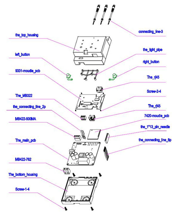
Fig 9. Exploded view of MGE. See RDOC-MEC-11 and RDOC-MEC-10
9.1 Parts
The mechanical enclosure is composed of 6 plastic parts.
REQ-MEC-0010: General protection against fire
(EMS design asked)
Plastics parts must be compliant with RDOC-MEC-8.
REQ-MEC-0020: Material of plastic parts must be flame retardant (EMS design asked)
Materials used for plastic parts must have grade V-2 or better according RDOC-MEC-7.
REQ- MEC-0030: Material of connectors must be flame retardant (EMS design asked)
Materials used for connectors parts must have grade V-2 or better according RDOC-MEC-7.
REQ-MEC-0040: Openings inside the mechanicals
It mustn’t have holes except for:
– Connectors (must have less of 0.5mm of mechanical clearance)
– Hole for Factory reset (1.5mm)
– Holes for temperature dissipating (diameter of 1.5mm spaced of 4mm minimum) around Ethernet connectors faces (see figure below).
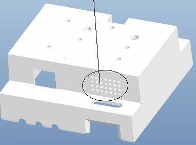
Fig 10. Example of holes on the external enclosure for heating dissipation
REQ-MEC-0050: Color of parts
All plastics parts must be white without other requirements.
REQ-MEC-0060: Color of buttons
Buttons must be blue with the same shade of the MLS logo.
REQ-MEC-0070: Drawings
The housing must respect the plans RDOC-MEC-1, RDOC-MEC-2, RDOC-MEC-3, RDOC-MEC-4, RDOC-MEC-5, RDOC-MEC-6
REQ-MEC-0080: injection mold and tools
(EMS design asked)
The EMS is allowed to manage the full process for plastic injection.
Plastic injection inputs/outputs marks mustn’t be visible from the external of the product.
9.2 Mechanical assembly
REQ-MEC-0090: Light pipe assembly
The light pipe must be assembled using a hot source on melting points.
The external enclosure must be melted and visible inside dedicated melting points holes.
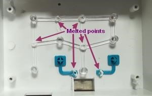
Fig 11. Light pipe and buttons assemblies with hot source
REQ-MEC-0100: Buttons assembly
Buttons must be assembled using a hot source on melting points.
The external enclosure must be melted and visible inside dedicated melting points holes.
REQ-MEC-0110: Screw on top enclosure
4 screws are used to fix the AR9331 board to the top enclosure. See RDOC-MEC-11.
Used the reference inside RDOC-MEC-10.
The tightening torque must be between 3.0 and 3.8 kgf.cm.
REQ-MEC-0120: Screws on bottom assembly
4 screws are used to fix the main board to the bottom enclosure. See RDOC-MEC-11.
Same screws are used to fix enclosures between them.
Used the reference inside RDOC-MEC-10.
The tightening torque must be between 5.0 and 6 kgf.cm.
REQ-MEC-0130: CT probe connector way through the enclosure
The trough wall part of the CT probe connector must be corrected assembled without pinch to allow good hermeticity and good robustness against unwanted wire pulling.
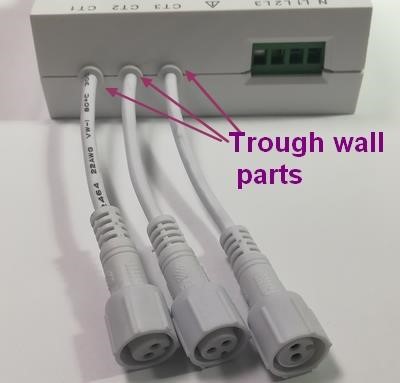
Fig 12. Trough wall parts of CT probes
9.3 External silkscreen
REQ-MEC-0140: External silkscreen
Below silkscreen must be done on the top enclosure.
Fig 13. External silkscreen drawing to be respected
REQ-MEC-0141: Color of the silkscreen
The color of the silkscreen must be black except for the MLS logo which must be blue (same color than buttons).
9.4 Labels
REQ-MEC-0150: Serial number bar code label dimension
– Dimension of the label: 50mm*10mm
– Text size: 2mm height
– Bar code dimension: 40mm* 5mm
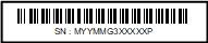
Fig 14. Example of serial number bar code label
REQ-MEC-0151: Serial number bar code label position
See External silkscreen requirement.
REQ-MEC-0152: Serial number bar code label color
The serial number label bar code color must be black.
REQ-MEC-0153: Serial number bar code label materials
(EMS design asked)
The serial number label must be glued and information mustn’t disappear according to RDOC-MEC-9.
REQ-MEC-0154: Serial number bar code label value
The serial number value must be given by MLS either with the manufacturing order (personalization file) or through a dedicated software.
Below the definition of each character of the serial number:
| M | YY | MM | XXXXX | P |
| Master | Year 2019 =19 | Month= 12december | Sample numberfor each batcheach month | ManufacturerReference |
REQ-MEC-0160: Activation code bar code label dimension
– Dimension of the label: 50mm*10mm
– Text size: 2mm height
– Bar code dimension: 40mm* 5mm
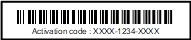
Fig 15. Example of activation code bar code label
REQ-MEC-0161: Activation code bar code label position
See External silkscreen requirement.
REQ-MEC-0162: Activation code bar code label color
The activation code bar label code color must be black.
REQ-MEC-0163: Activation code bar code label materials
(EMS design asked)
The activation code label must be glued and information mustn’t disappear according to RDOC-MEC-9.
REQ-MEC-0164: Serial number bar code label value
The activation code value must be given by MLS either with the manufacturing order (personalization file) or through a dedicated software.
REQ-MEC-0170: Main label dimension
– Dimension 48mm*34mm
– Symbols have to be replace by the official design. Minimun size : 3mm. See RDOC-MEC-9.
– Text size: minimum 1.5
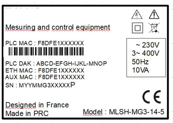
Fig 16. Example of main label
REQ-MEC-0171: Main label position
The main label must be positioned on the side of MG3 on the dedicated room.
The label must be above top and bottom enclosure in a way to not allowed openings of enclosure without label removing.
REQ-MEC-0172: Main label color
The main label color must be black.
REQ-MEC-0173: Main label materials
(EMS design asked)
The main label must be glued and information mustn’t disappear according to RDOC-MEC-9, especially safety logo, power supply, Mylight-Systems name and product reference
REQ-MEC-0174: Main label values
The main label values must be given by MLS either with the manufacturing order (personalization file) or through a dedicated software.
Values/text/logo/inscription must respect the figure in REQ-MEC-0170.
9.5 CT probes
REQ-MEC-0190: CT probe design
(EMS design asked)
The EMS is allowed to design itself CT probes cables, including female cable attached to MG3, male cable attached to CT probe and the extension cable.
All drawing must be given to MLS
REQ-MEC-0191: Material of CT probes parts must be flame retardant (EMS design asked)
Materials used for plastic parts must have grade V-2 or better according CEI 60695-11-10.
REQ-MEC-0192: Material of CT probes parts must have cable isolation Materials of CT probes must have double 300V isolation.
REQ-MEC-0193: CT probe female cable
Female contacts must be isolated from the accessible surface with 1.5mm minimum (diameter maximal of the hole 2mm).
Color of the cable must be white.
The cable is soldered from one side to MG3 and on the other side must have a lockable and codable female connector.
The cable must have a crimped pass-through part which will be used to go across the plastic enclosure of the MG3.
Length of the cable must be around 70mm with the connector after the pass-through part.
MLS reference of this part will be MLSH-MG3-22
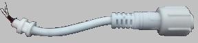
Fig 18. CT probe female cable example
REQ-MEC-0194: CT probe male cable
Color of the cable must be white.
The cable is soldered from one side to the CT probe and on the other side must have a lockable and codable male connector.
Length of the cable must be around 600mm without the connector.
MLS reference of this part will be MLSH-MG3-24
REQ-MEC-0195: CT probe extension cable
Color of the cable must be white.
The cable is soldered from one side to the CT probe and on the other side must have a lockable and codable male connector.
Length of the cable must be around 3000mm without connectors.
MLS reference of this part will be MLSH-MG3-19
REQ-MEC-0196: CT probe reference
(EMS design asked)
Several references of CT probe could be used in the future.
The EMS is allowed to deal with the CT probe manufacturer to assemble the CT probe and the cable.
Reference 1 is MLSH-MG3-15 with:
– 100A/50mA CT probe SCT-13 from YHDC manufacturer
– MLSH-MG3-24 cable
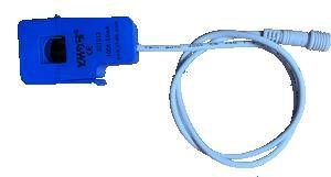
Fig 20. CT probe 100A/50mA MLSH-MG3-15 example
10 Electrical Tests
| Electrical tests documents | |
| REFERENCE | DESCRIPTION |
| RDOC-TST-1. | PRD-0001-MG3 test bench procedure |
| RDOC-TST-2. | BOM-0004-BOM file of MG3 test bench |
| RDOC-TST-3. | PLD-0008-PLD of MG3 test bench |
| RDOC-TST-4. | SCH-0004-SCH file of MG3 test bench |
10.1 PCBA testing
REQ-TST-0010: PCBA testing
(EMS design asked)
100% of electronic boards must be tested before mechanical assembly
Minimum functions to test are:
– Power supply isolation on main board between N/L1/L2/L3, main board
– 5V, XVA (10.8V to 11.6V), 3.3V (3.25V to 3.35V) and 3.3VISO DC voltage accuracy, main board
– Relay is well open when no power, main board
– Isolation on RS485 between GND and A/B, AR9331 board
– 120 ohm resistance between A/B on RS485 connector, AR9331 board
– VDD_DDR, VDD25, DVDD12, 2.0V, 5.0V and 5V_RS485 DC voltage accuracy, AR9331 board
– VDD and VDD2P0 DC voltage accuracy, AR7420 board
The detailed PCBA test procedure must be given to MLS.
REQ-TST-0011: PCBA testing
(EMS design asked)
The manufacturer can manufacture a tool to do these tests.
The definition of the tool must be given to MLS.
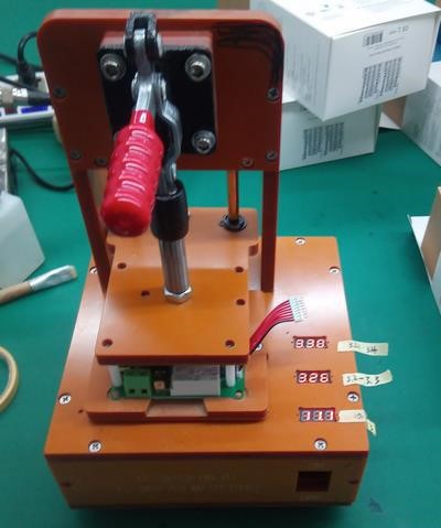
Fig 21. Example of tooling for PCBA testing
10.2 Hipot testing
REQ-TST-0020: Hipot testing
(EMS design asked)
100% of devices must be tested after final mechanical assembly only.
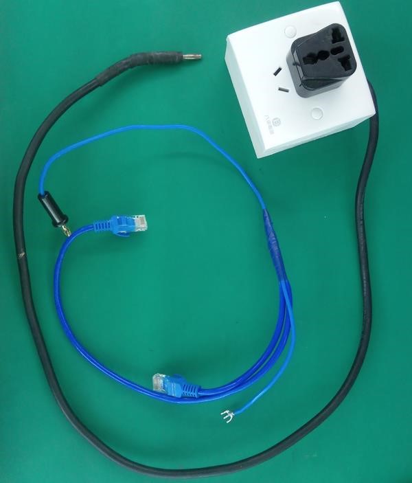
If a product is disassembly (for rework/repair as exemple) it must do the test again after mechanical reassembly. High Voltage isolations of Both Ethernet port and RS485 (first side) must be tested with the power supply (second side) on all conductors.
So one cable is connected to 19 wires : Ethernet ports and RS485
The other cable is connected to 4 wires : Neutral and 3 phases
EMS must do a tool to have all conductors off each side on the same cable in order to do only one test.
DC 3100V voltage must be applied. 5s maximum to set the voltage and then 2s minimum to maintain the voltage.
No current leakage is allowed.
Fig 22. Cable tool in order to have easy Hipot test
10.3 Performance PLC test
REQ-TST-0030: Performance PLC test
(EMS design asked or designed with MLS)
100% of devices must be tested
The product must manage to communicate with another CPL product, as an PL 7667 ETH plug, through a 300m cable (can be winded).
Data rate measured with script “plcrate.bat” must be above 12mps, TX and RX.
In order to have easy pairing please use script “set_eth.bat” which set MAC to “0013C1000000” and NMK to “MyLight NMK”.
All tests must take 15 / 30s maximum including power cable assembly.
10.4 Burn-In
REQ-TST-0040: Burn-In condition
(EMS design asked)
Burn-In must be done on 100% of electronic boards with following conditons:
– 4h00
– 230V power supply
– 45°C
– Ethernet ports shunted
– Several products (at least 10) in same time, same powerline, with same PLC NMK
REQ-TST-0041: Burn-In inspection
– Every hour check led are blinking and relay can be activated/deactivated
10.5 Final assembly test
REQ-TST-0050: Final assembly test
(At least one test bench is provided by MLS)
100% of products must be tested on the Final assembly test bench.
Test time is supposed to be between 2.30min and 5min following optimizations, automatization, experience of the operator, different issue which can happen (as firmware update, communication issue with an instrument or stability of the power supply).
Main aim of the final assembly test bench is to test:
– Power consumption
– Check version of firmwares and update them if needed
– Check PLC communication through a filter
– Check buttons : Relays, PLC, Factory reset
– Check leds
– Check RS485 communication
– Check Ethernet communications
– Do power measurements calibrations
– Write configurations numbers inside the device (MAC address, Serial number)
– Configure the device for delivery
REQ-TST-0051: Final assembly test Manual
The test bench procedure RDOC-TST-1 must be well read and understood before use in order to ensure:
– Safety of the user
– Correct use the test bench
– Performance of the test bench
REQ-TST-0052: Final assembly test Maintenance
Operation of maintenance of the test bench must be done in conformity with RDOC-TST-1.
REQ-TST-0053: Final assembly test Label
A sticker/label must be glued on the product as described in RDOC-TST-1.
Fig 23. Final assembly test label example
REQ-TST-0054: Final assembly test Local Data base
All logs stored in the local computer must be sent to Mylight Systems regularly (at least one time a month or one time per batch).
REQ-TST-0055: Final assembly test Remote Data base
The test bench must be connected to the internet in order to be able to send logs to a remote data base in real time. Full cooperation of the EMS is wanted to allow this connection inside its internal communication network.
REQ-TST-0056: Reproduction of the test bench
MLS can send several test benches to the MES if needed
The EMS is also allowed to reproduce the test bench itself according RDOC-TST-2, RDOC-TST-3 and RDOC-TST-4.
If the EMS want to do any optimization it must ask MLS the authorization.
Reproduced test benches must be validated by MLS.
10.6 SOC AR9331 programming
REQ-TST-0060: SOC AR9331 programming
The memory of the device must be flashed before assembly with a universal programmer not provided by MLS.
The firmware to be flashed must be always and be validated by MLS before each batch.
No personalization is asked here, so all devices have the same firmware here. Personalization will be done later inside the final test bench.
10.7 PLC chipset AR7420 programming
REQ-TST-0070: PLC AR7420 programming
The memory of the device must be flashed before burning tests in order to have the PLC chipset activated during the test.
The PLC chipset is programmed via a software given by MLS. The flashing operation take around 10s. So the EMS can consider maximum30s for the whole operation (Cable power + Ethernet cable + Flash + Remove cable).
No personalization is asked here, so all devices have the same firmware here. Personalization (MAC address and DAK) will be done later inside the final test bench.
The PLC chipset memory can also be flashed before assembly (to try).